Pingbox and network setup
Deploy the Swift Fox pingbox (VM, Raspberry Pi, cloud tunnel, or embedded device), add device credentials, build your network map, and prepare your MikroTik core router for monitoring and automation.
Setting up the Pingbox
In order for Swift Fox to be able to monitor your network and perform automated tasks, you’ll need to have a Pingbox connected to your network. The easiest way to do this is by using a “Cloud Pingbox”, which has the pingbox run on a server in the cloud managed by Swift Fox, with a tunnel configured to an edge router on your network. To configure this, simply open Network → Settings → Manage Pingboxes in Swift Fox and follow the instructions.
If you have a server that is always turned on, and located near your network edge — an easy way to have on-premises monitoring is to run a virtual machine image. Alternatively you can order a physical pingbox, a small energy-efficient device based on a Raspberry Pi 5 that can easily fit in most cabinets.
Steps for Installing VM Pingbox with VirtualBox
- Download and install the latest version of the VirtualBox software
- Open the Manage Pingboxes page in Swift Fox and click the “Download .OVA Image” button. If you have already set up a pingbox, click the name of it and ensure the Pingbox Type is set to “Virtual Machine: .OVA VirtualBox Image”.
- Wait for the pingbox image to be created, and click the Download button when it is finished to get a .OVA file
- Open the .OVA file, and accept the default import settings that VirtualBox suggests
- Click the pingbox on the left side and press the “Start” button at the top. This will launch your pingbox, by default with DHCP and behind an internal NAT. For most purposes this will work fine, but there are a few circumstances where you will need to change it (see “Setting up the Pingbox Virtual Machine for Push Features” below.)
- If you plan to use VirtualBox on this server long-term and not just for evaluation, you’ll want to ensure it launches the VM at boot. This varies by operating system, so you may have to google to find how it is done
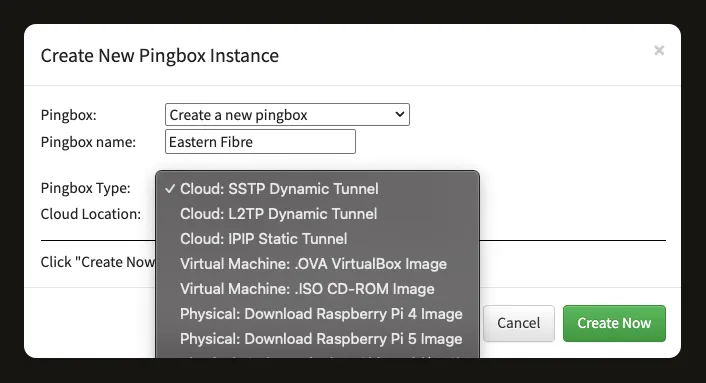
The Create New Pingbox Instance dialog — pick a cloud tunnel, VM image, Raspberry Pi image, or order a physical device.
Steps for Installing VM Pingbox with ProxMox VE
- Open the Manage Pingboxes page in Swift Fox and click the “Download .ISO Image” button. If you have already set up a pingbox, click the name of it and ensure the Pingbox Type is set to “Virtual Machine: .ISO CD-ROM Image”
- Wait for the pingbox image to be created, and click the Download button when it is finished to get a zip file. Unzip this to get a .ISO file.
- Log into your ProxMox instance and click your storage on the left (might be called “local”), then select “ISO Images” and click the “Upload” button. Select the ISO file you downloaded earlier and click Upload
- Click the “Create VM” button in the top-right, and use the following
settings:
- General — Name: SwiftfoxPingbox
- OS — Use CD/DVD disc ISO image: (select the ISO you uploaded), Guest OS Type: Linux, Guest OS Version: 6.x - 2.6 Kernel
- Hard Disk — click the trash can next to scsi0, as this does not use a hard disk
- CPU — Sockets: 1, Cores: 2
- Memory — 1024 MiB
- Network — Bridge: vmbr0 (or whatever your default bridge is), Model: VirtIO (paravirtualized), uncheck Firewall
- Confirm — Check the “Start after created” checkbox
- Go back to the SwiftfoxPingbox VM in the Proxmox interface and in the “Options” menu, enable “Start at boot”
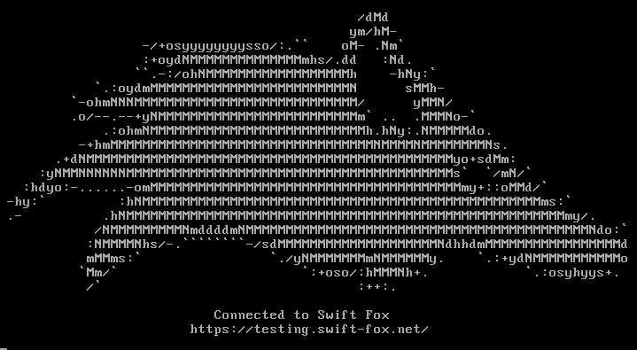
- Check the console for the VM and if you see the Swift Fox logo, it should be good to go.
Steps for Installing VM Pingbox with Other Virtualization Software
- Download the pingbox .ISO file from the Manage Pingboxes page in Swift Fox
- Create a Linux 6.x (64-bit) compatible virtual machine with at least 1GB of RAM and preferably at least 2 cores, set to boot from the .ISO image as a virtual CD-ROM. The best network interface to use is VirtIO, but a range of common ones are supported if this one isn’t available.
- Run the VM image and ensure that it connects properly
If you have successfully started your VM pingbox, you should see a screen that looks like the following. Your network map status page in Swift Fox will also turn green.
Setting up the Pingbox Virtual Machine for Push Features in VirtualBox
There are a number of Swift Fox features that require the pingbox to be reachable on your network (eg. not behind a NAT within the VM environment). Features such as automatic Ubiquiti firmware updates, netflow traffic monitoring, and TZSP latency monitoring all require this ability. To set this up, you’ll need to make sure that the VM instance is bridged onto your network and has a reachable IP assigned to it. The following steps will ensure this in VirtualBox:
- On the main VirtualBox window, click your pingbox on the left, and then click the “Network” heading on the right
- In the dropdown beside “Attached To:”, change it from NAT to “Bridged Adapter”
- Below that, select the adapter that provides this computer with network access and click OK
- Start the pingbox up again. If you have DHCP available on this network, just wait for it to boot and you’ll be ready
- If you require a static IP address on the pingbox, configure it on the Manage Pingboxes page and download a new ISO with that IP in it
Changing IP settings on the embedded hardware pingbox
The physical embedded pingbox (small black one) will be pre-configured however it was requested when ordered, but if you need to change the IP settings:
- Download and install Balena Etcher
- Unplug power from the embedded pingbox and remove its MicroSD card
- Insert the MicroSD card into a card reader on your computer
- Click the pingbox on the Manage Pingboxes page and make sure the Pingbox Type is set to “Physical: Download Raspberry Pi 5 Image”
- Change the “IP Assignment” to either “DHCP” or “Static” and configure the static IP information in here if required, then click “Apply Changes”
- Click “Create Raspberry Pi 5 SD Card Image”, wait for it to create, and then click the download button to get a zipped .IMG file
- Unzip this file, and then use Balena Etcher to write it to the MicroSD card that you have inserted
- Put the MicroSD card back into the pingbox, plug the power back on, and confirm it is working
Network Credentials
In order to gather network information such as frequencies, config backups, ARP and bridge tables, and much more, Swift Fox needs to be able to log into your network equipment automatically. To do this, it needs to keep a record of the logins to use for each device. To add new logins, simply go to the Equipment Credentials page under Network → Settings.
You will want to add all of the logins that you use for infrastructure equipment, as well as for customer radios.
Customer Radio Logins
Most ISPs use the same credential for all customer radios, but sometimes this can drift over time as new firmwares enforce higher security passwords. When you create a credential in Swift Fox, you can click the “Use for CPE Logins” box and it will automatically be tried when logging into customer radios. The credentials that eventually ended up working for each CPE will show in the “Assigned CPEs” list and you can click this to see which CPEs have it assigned (useful for rolling out password changes)
While editing the credential if you click on “Advanced”, you can also set it to only try to use this credential for specific CPE manufacturer types (this is determined by the manufacturer or the AP the CPE is connected to)
Custom Login Ports
Swift Fox also supports associating a custom login port per credential, which lets you easily reach devices if your network overrides the default SSH, HTTP/S, or SNMP port for devices. This can also be overridden on a per-device basis for infrastructure on the netmap.
Password Visability
By default, credential passwords are masked for security, but an administrator can choose to enable “Network - View Credentials” as an ACL rule in the Admin → Access Control menu, if you would like to see the full password shown. If this is enabled, a button to copy to clipboard appears to assist in logging into devices using other tools or tabs.
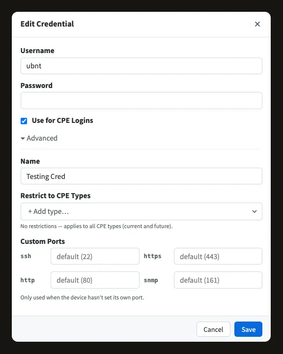
Equipment credentials with the Set CPE Default option.
Add Infrastructure To Netmap
The network map is the main page for configuring, managing, and monitoring your network in Swift Fox. You can reach it by simply clicking on the Network link on the left bar, and it will be the first page that loads when you log into Swift Fox.
New ISPs created in Swift Fox will have two example sites, with a handful of devices connected together to demonstrate how the network map works. Feel free to delete these before you add your own devices, or just create your new sites alongside them and delete them afterwards.
The network map has two main views, the Status view — which shows the real-time status of your devices and how they connect to each other, and the Map view which shows the physical locations of the sites and customers.
Adding Network Sites
A “site” in Swift Fox is defined as a distinct physical location. It might be a tower in the countryside, or your fibre colocation facility in the city. It’s essentially any place that has its own location. The first thing you’ll want to do in setting up your network is to add all of your network sites. For larger ISPs, contact Swift Fox and we can assist in importing these automatically.
- On the Network Map, right-click an empty space on the sites view, then click “Add Site”. You can also click the “Edit” button in the top-right, and then click the ”+ Site” button in the top-left.
- Enter a description, like “Springfield North”, and pick a short code — preferably three characters, like “SPN” to refer to this site. The short code will be used to quickly identify backhaul links and access points throughout Swift Fox
- If this is a wireless site, enter the approximate average height of the antennas above ground level in the “Height AGL” box. This will help provide accurate line of sight plots to customers
- If you know the exact GPS coordinates of the site, enter them here, if not you can either place it from the Map view afterwards, or you can wait until a GPS-enabled device is added to the site (like an AP) and it will auto assign the coordinates it has.
- Drag the newly created site to somewhere that makes sense on the screen, and click “Done” in the top-right if you are done adding sites.
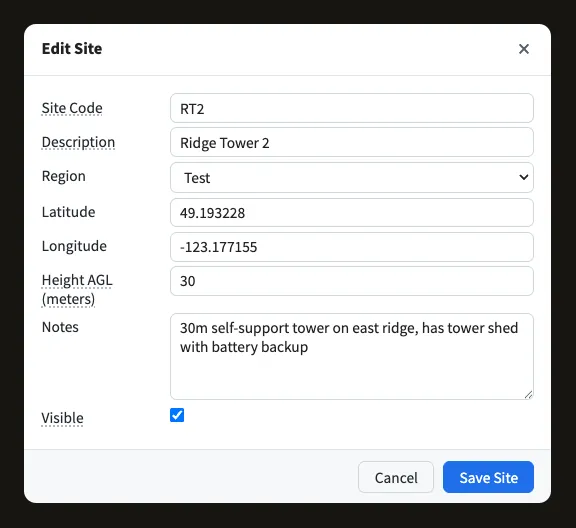
The site dialog on the network map.
Adding Infrastructure Devices
Once your sites are created, you’ll want to add all of the equipment at each site. This is usually easiest to do by starting from your core router and working towards the edges of your network.
- On the Network Map, click on one of your sites to open it up.
- Right-click an empty space on the netmap, then click “Add Device”. You can also click the “Edit” button in the top-right, and then click the ”+ Device” button in the top-left.
- Enter a description for this device, such as “Springfield Router”
- Make sure the Hardware type is set correctly. If your type is not available, set it to Generic and contact Swift Fox to have it added.
- Set the Type accordingly. Click the label for Type to get a thorough explanation of what the different types do. In general, APs are what customer radios will connect to, and Backhauls connect sites together. If an AP serves both customers and other sites (‘subscriber-repeater’ arrangement), then configure the AP as an AP, and the other site radios as Backhaul SU.
- Set the IP address that Swift Fox will use to log into this. The interface name is optional
- Pick the upstream device — this is whichever device is next upstream towards the Internet. Swift Fox uses this to determine how to page out in the event of network outages, and to draw lines between devices and sites on the network map. If this device has multiple upstreams just pick one of them, you can add the rest with the backhaul functionality.
- Set the login to be used for this device, this is based on what you have set up earlier on the Equipment Credentials page. You can also add a new credential from this menu by clicking ”+ Add new credential”
- For access points, it will ask you for a range of IP addresses that CPEs should exist on. By default this is only used to suggest free IP addresses when adding new CPEs, for installers to be able to statically assign them. If you use DHCP for customer radios, then Swift Fox will automatically find the assigned ones. The checkbox for “Only detect radios within the above IP range” should only be enabled if you want to ignore IPs for MAC addresses that are outside that range (some configs where radios have multiple IPs bound to each wireless interface, or where Proxy-ARP is used)
- Click “Create Device”, and then drag and resize this device into a good spot. As you add more devices, lines will appear between them and you will want to rearrange things so that they’re clear to understand. Click “Done” when you’re finished.
Configure Core Router
Swift Fox requires a Mikrotik core router in order to do bandwidth tracking, captive portal disconnects, and automatic traffic shaping to customer package speeds. In order to facilitate this, there are a few config changes that will need to be made to your router.
Enable the Edge Router in Swift Fox
By enabling the edge router, you will have the option to have Swift Fox insert IP addresses into the “sf-disconnect” address list, as well as simple queue entries for every CPE. It can also download IP accounting data in order to calculate bandwidth usage for customers, or receive netflow data for the same purpose. Other features can be enabled or disabled individually.
- Find your core router on the Network Map, and right click it, select “Edit Device”.
- Make sure that the “Network Edge Router” checkbox is enabled
- Also make sure that a login has been specified
- Ensure that the main public IP address of your core router is included as either the main IP or one of the additional IPs in this device.
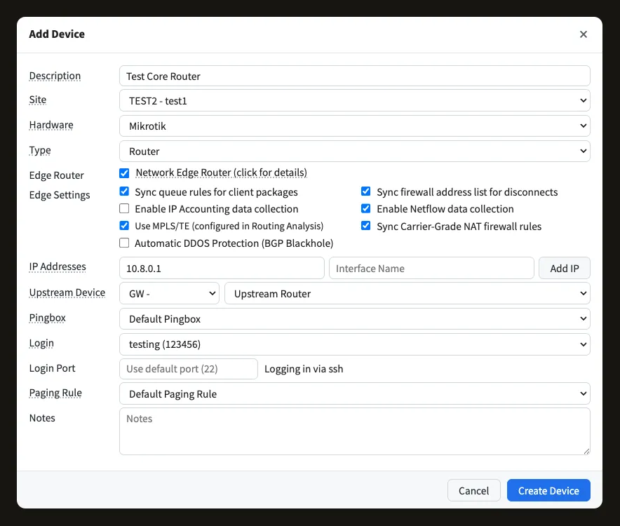
The Add Device dialog with Network Edge Router enabled — edge settings control shaping, disconnects, NetFlow, and MPLS/TE sync.
Paste In Captive Portal Config
These firewall rules will cause customers that are disconnected in Swift Fox to get redirected to a page asking them to check their account. This will allow them to log into and pay their bill, but not access anything else on the Internet.
- Log into your router by WebBox or Winbox (or SSH if you’re familiar with the command line interface)
- Click “Safe Mode” in the toolbar. This prevents you from locking yourself out if you accidentally make the wrong config change.
- Copy and paste the following into the Mikrotik console:
/ip firewall address-list
add list=captive-allowed-ips address=172.105.17.29 comment="Swift Fox Server"
add list=captive-allowed-dns address=8.8.8.8 comment="Google DNS"
add list=captive-allowed-dns address=8.8.4.4 comment="Google DNS (secondary)"
add list=captive-allowed-dns address=1.1.1.1 comment="Cloudflare DNS"
add list=captive-allowed-dns address=1.0.0.1 comment="Cloudflare DNS (secondary)"
add list=captive-allowed-dns address=9.9.9.9 comment="Quad9 DNS"
add list=captive-allowed-dns address=149.112.112.112 comment="Quad9 DNS (secondary)"
add list=captive-allowed-dns address=208.67.222.222 comment="OpenDNS"
add list=captive-allowed-dns address=208.67.220.220 comment="OpenDNS (secondary)"

/ip firewall filter
add action=accept chain=forward src-address-list=captive-allowed-ips
add action=accept chain=input src-address-list=captive-allowed-ips
add action=jump chain=forward packet-mark=captive-disconnect jump-target=Captive_Rules
add action=accept chain=Captive_Rules dst-address-list=captive-allowed-ips
add action=accept chain=Captive_Rules dst-address-list=captive-allowed-dns dst-port=53 protocol=tcp
add action=accept chain=Captive_Rules dst-address-list=captive-allowed-dns dst-port=53 protocol=udp
add action=reject chain=Captive_Rules reject-with=icmp-net-prohibited

/ip firewall mangle
add action=mark-connection chain=prerouting new-connection-mark=captive-disconnect passthrough=yes src-address-list=sf-disconnect
add action=mark-packet chain=prerouting connection-mark=captive-disconnect new-packet-mark=captive-disconnect passthrough=yes

/ip firewall nat
add action=dst-nat chain=dstnat dst-address-list=!captive-allowed-ips dst-port=80 packet-mark=captive-disconnect protocol=tcp to-addresses=172.105.17.29 to-ports=5080
add action=dst-nat chain=dstnat dst-address-list=!captive-allowed-ips dst-port=443 packet-mark=captive-disconnect protocol=tcp to-addresses=172.105.17.29 to-ports=5443
The paste creates two address lists you can extend by hand:
captive-allowed-ips— IPs that disconnected customers can always reach (and that are exempt from being NATted to the captive page). Add your home/office IP, your billing portal IP, anything else you want always reachable.captive-allowed-dns— DNS servers disconnected customers can query. Pre-populated with the major public resolvers (Google, Cloudflare, Quad9, OpenDNS). If you operate your own recursive resolver or hand out provider-specific DNS via DHCP, add those here too.
Add custom entries via Winbox/WebBox under IP → Firewall → Address Lists → Add New, picking the matching list name from the dropdown.
Add The Final Captive Config Rule
After the above is pasted, do the following. This couldn’t be part of the above paste because it relies on a setting that is specific to your router.
- Under IP → Firewall → NAT
- Click “Add New”
- Set the Chain to “srcnat”
- Under Out Interface, click the triangle and select the interface that your upstream gateway is plugged into
- Under Packet Mark, click the triangle and select “captive-disconnect” from the dropdown.
- At the bottom, find the dropdown for Action and change it to “masquerade”
- Click OK to save
- Click the “Safe Mode” button again in the toolbar to turn off safe mode and permanently apply the settings